Saturday, 24 January 2015

Game Engine Testing and Scaling Issues

After having a discussion with my supervisor last week, I've realised that there are a few technical areas of my project that need to be considered, which I will talk about and show work that I have currently done for these issues.

The first of which is FPS (Frames Per Second), the optimum frame rate of which a scene can run at containing game assets, lighting, and so on. My latest model iteration stands at 354, 145 polys and 713, 422 tris. This is largely in part due to the tank treads, which I will be creating iterations off in order to reduce the poly count. Regardless, this would be too high for an in game asset, and be more appropriate for a cinematic cutscene instead.

Through doing a little research on the polycounts of vehicles in games today, I found that there a lot of factors to consider. Elements such as the console platform the game is being made for, the genre and the game engine used play a big part. So whilst there are games with lots of character that use vehicles, such as lost planet, with 30,000-40,000 for its robots, there are others like Forza 4 with a minimum of 400,000 to 1 million polys. These factors have an important part to play in a vehicles construction.

Article on Kotaku that talks about Forza Motorpsport 4's features, including the 400,00 to 1 million poly counts for its vehicles. 
So I've decided that I will continue to model the high poly model, texture it, and then create an optimised lower poly count version that could be used for in game. This will allow me to show off the model, but at the same time show off its practicality as well. In terms of a platform, this model would most like be for be used in a Xbox One or PS4 console title.

Also, Deciding on how it would function in game is important. For instance, a game with just robots fighting would allow for a higher poly, whereas if its a drive able vehicle in say a First person shooter would have to have a lower poly count, to make by for any other vehicles on characters poly counts in the same area.

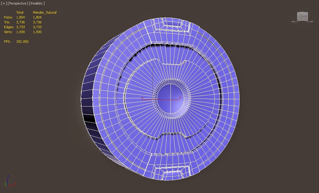
In the meantime, I found that testing the frame issue was important. In 3ds max alone, panning around the model can make the FPS leap between 70-110 fps. For an optimum result, 60 FPS would be best for an in game model. There's some topology that could easily be scaled back to help with this issue, though this mainly affects the low poly model rather than the high poly model.

In order to test the FPS, I decided to implement  my current model into two game engines: UDK, and Unreal Engine 4.

My first test was in UDK. To begin with, I exported the entire model merged together as an FBX in 3DS MAX, and attempt to import it into UDK. However, my first attempt failed, as it turns out for a single asset UDK can only handle a maximum of 65, 535 faces or verts on a model. So I had to go back into Max, split up the pieces further, and re-import into UDK. This took a few attempts to get right.

Once in the standard UDK scene, I found a few issues. First, it was obvious that my scale was off. Since I've been working on the design currently by eye, I have yet to set a proper scale for the model, so this is something to be dealt with in the coming days. Also, certain parts came in with visible modelling issues, such as the tank tread pieces.

UDK import issues. 

Model distortion issues with the tank treads.

Working pieces in UDK, but with the wrong scale.

Correct scale, and looked pretty good, but the fps issues were a problem.

UDK full model 2.


However, I was able to place all the working pieces together and get an idea of how it would look. Unfortunately, the frame rate  was sticking to a constant 108-120 fps, which wouldn't work well for a in game scene. Safe to say, it was quite the hassle getting the model into UDK, and has made me realise it's not the best choice for my High-poly model.

In comparison, Unreal Engine 4 was far more successful. There were no issues when it came to importing the model, and I also discovered it automatically brings in textures attached to the model in the export, which saves time have to manually bring these in separately from the model. Although again the scale was off, it was easy to scale down. Also, UE 4 had no problems frame rate wise, easily running with my model in the scene at a steady 30fps. So when it comes to implementing the model in engine, I'll definitely be making use of Unreal Engine 4 for this task.

UE4 Screenshot 1.

UE4 Screenshot 2.


In regards to my earlier comment about the scale of my model, its become clear that clarifying this issue is paramount to my work. To begin with, if the scale is drastically off, i'll have to rescale each piece separately, and have to rest the x-forms, otherwise it will cause texture issues in the long run. Also, getting a correct sense of scale will make it clearer to the viewer exactly how big it is. So for the time being, I have modeled a basic ladder to give you a sense of scale, as ladders a good comparison object in relation to a human's height.

Tank model with the added ladder, which gives a better idea of its size. 

So as the post shows, its not just about making a pretty looking model, but one that functions as well as it looks. By having taken these aspects into consideration, I will be able to make much more efficient models for this project overall.

Further updates to come.


Wednesday, 21 January 2015

Military Robotic Mech Modelling 2

In this blog entry I will show further 3D modelling work done for the robotic mech.

I started by deciding to create a modular system for my RM. These will be made up largely of external pieces that I can stick onto the main model pieces. Below shows some of the pieces already used in the model, some modified from previous models, such as the screws, and some new parts made recently, including the tank treads and smoke grenade launcher, which I will talk about in this post.

Modular pieces kit. 


With the the tank grenade launcher, I found an excellent reference diagram online to 3D model from. I started by following the basic shape, using the chamfer tool to create the extra edges and the circles to extrude the tubes from, and edited out any topology issues. I constantly switched between the low poly model and the turbosmooth modifier to see how it would look in high poly.


Smoke Grenade Launcher Diagram.
Modelling progression of the first launcher. 

However, I found that I didn't really like the design I had created, and instead went on to create my own version based of other internet reference and my own ideas.

I elongated and added extra launching tubes, and made them all face the same direction. I was a lot happier with this design, and once finished, added it on to my model in progress, as shown below.

Modelling Progression of the second launcher.

Launcher on the tank in progress.

With this out of the way, I decided to finally tackle the tank treads, which I knew would be  a challenge to model. Before and during this process, I found a lot of useful online references to help me with my modelling, as you can see below, I focused on making use of the
Abrams tank as it was a key reference that I used when I originally designed my concepts.


For my first attempt, I modeled the main tread piece. I used the original placeholder piece, made it smaller, and then duplicated it. I then edited the topology to make it match up with the online referencing, and used 3 cylinders to punch in the 3 holes needed for the other pieces. I then created the outer pieces, which hold the tread pieces in place, and finally the hook part which runs along the tanks wheels.


Modelling part 1.

Modelling part 2.

Modelling part 3.

However after my first attempt I realised that the pieces were too wide, and that the actual shape of the parts were different from what I had modelled. So I went through the process again and created tank tread pieces that I was happier with.

Redesigned tank tread.

With these done I tested out lining them up and creating a curve. Additionally I tested out different shapes that could be used for the top part of the tread. I discovered a few more issues/things that needed to be changed, and eventually settled on a new design in its 3rd iteration. Once finished, I added the treads to the tanks wheels, also changing the size and number of said wheels, and placed them on the model in progress.

Testing of curvature and different piece styles. 

Tank treads and wheels combined together. 


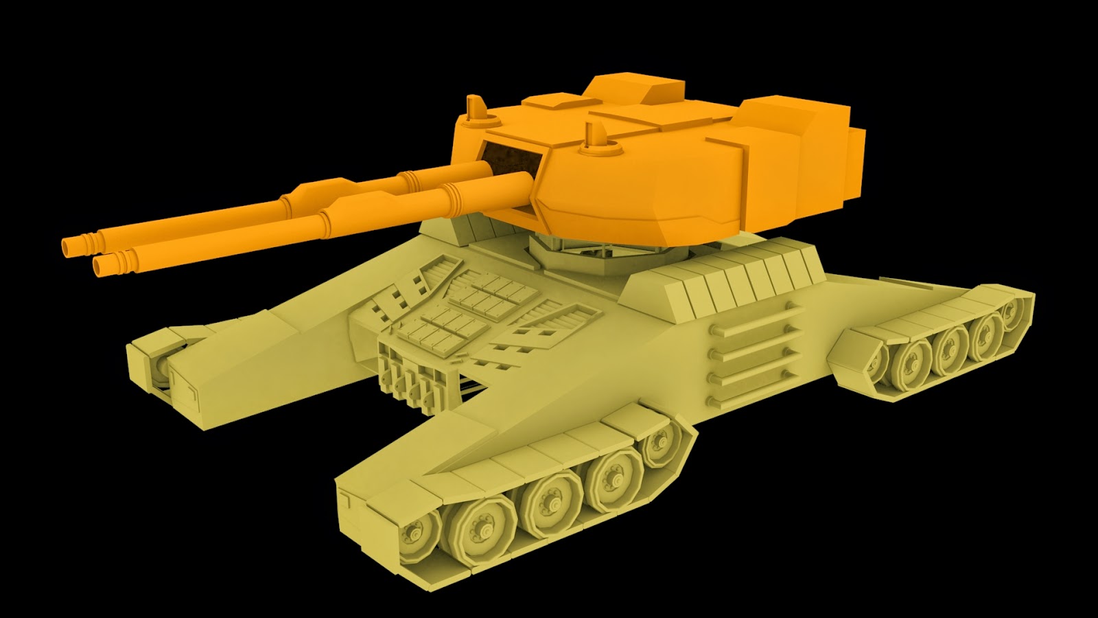
Also, same as last time, renders of the model in full have been provided to give you an idea of the overall progression thus far. Note the red pieces represent external parts not created directly on the main parts of the model.


I happy with the progress that has been made in this entry,with the base and torso sections getting closer to being completed modelling wise.

The next blog entry will contain further 3D work will be shown and potentially a brief exploration into texturing with the test head model as well.

Tuesday, 20 January 2015

Military RM modelling brief update

Brief update on work done for the military RM.

Made a few changes to the base model, adding a few extra elements such panels to the engine vents on the back, making the armour panel on the side feel like a separate piece through adding inward extrusions (suggestion of piece that clips on), and added more heavy armour panels onto the top of layer. All changes can be seen below:


Main amount of recent work has been applied to the turret. I went into further detail into the external red pieces. Also changed up the topology on the tank turret itself in order to make it flow and work better with the turbosmooth modifier, which now currently works better thanks to use of hard edges and the swift loop tool. Both can be seen below.

Turret without turbosmooth and external pieces.

Turret with turbosmooth modifier on. 


Further updates to come.

Military Robotic Mech Modelling 1

Carrying on from the last entry, I've gone on to model the mech in more detail. I've mainly been working on the base and torso sections, as shown in the image below.


For example, in this section, I've been working out the where the edges should connect, which parts should be extruded or chamfered, and have also brought in pieces from my practice construction files, such as my armour pieces, to work out where external parts should be placed. I've also done this with the tank treads and the tanks main cannon.


In this image, I've created the connecting point between the turret and the base of the mech. I did this by extruding a flat plane from the circle shape from the base, extruded again to get the right, cut shapes into it and the proceeded to cut those out to get the hollow shape.

The turret section hasn't been too challenging so far as I've been working out its shape mostly. The red pieces that I've pulled out could be turned into external pieces that I just move into place, rather than have directly on the model, in order to make edge flow and the overall shaping easier to do.

And lastly, to see how the mech looks put together so far, I duplicated pieces and welded them together. I then added a skylight to the scene, applied a light tracer to the render set-up, set the resolution to 1920 x 1080 (HDTV Size) and rendered it out from various angles, as shown below.


I'm quite pleased with how the model looks so far. There's still a lot to figure out, such as how to model tank treads, which pieces such be external or attached, and general topology issues, but for the time being, I'm happy with the progress thus far.

The next entry will show further progression on this 3D model.

Hard Surface Modelling Tutorials

As stated in the last post, I've started to model out the basic stages of the robotic mech. There was no need to create a turnaround sheet at this point, as I knew how I wanted to model the robotic mech. Also, its very likely the design will change during the modelling process, so I'll hold off doing turnaround art till I've confirmed the final look of the model.

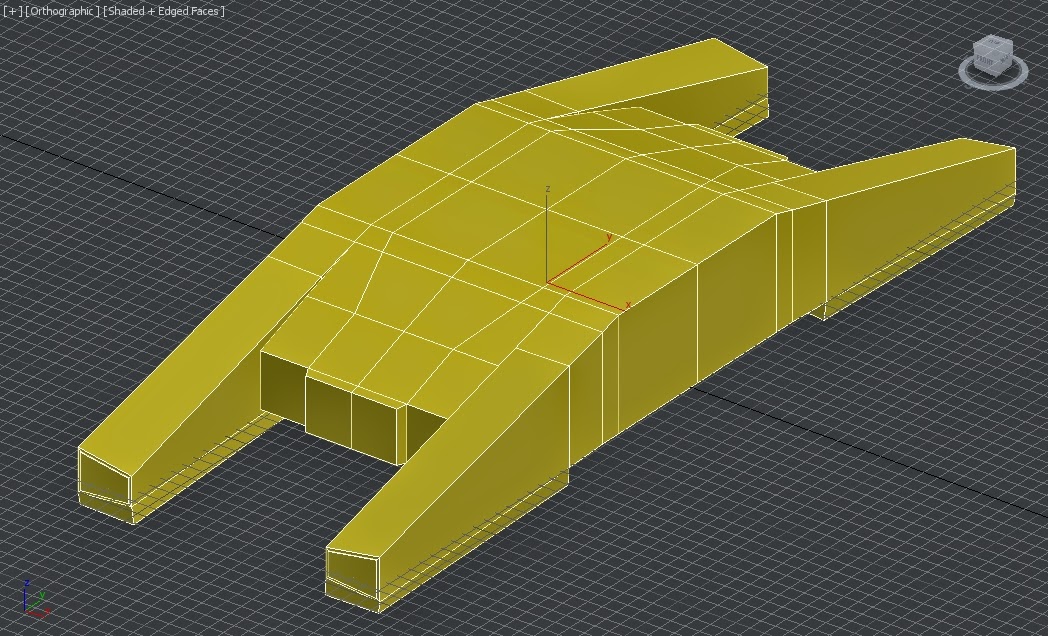
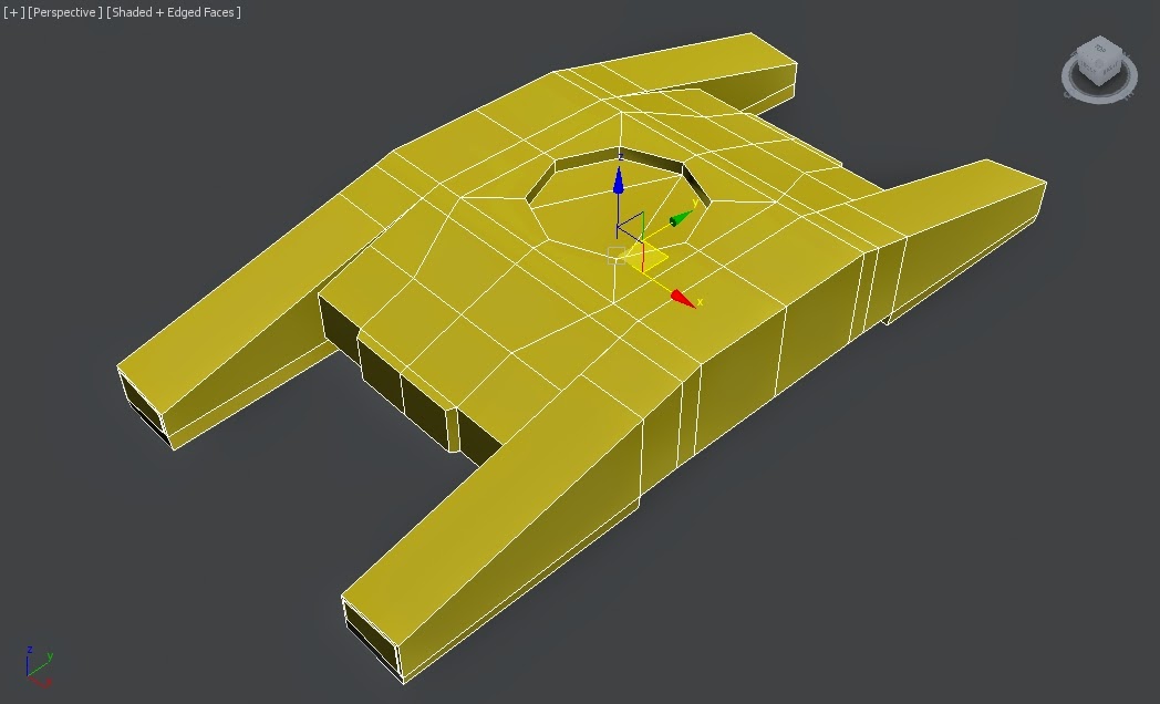
I started off with the base of the RM. This didn't take long to do, though the first version came out too thin, so I bulked it out using the scale turn for the 2nd attempt. Both are shown below. 
Version one follows the basic model outline of the blue print. The overall shape is right, but it turned out to be a little thin.

The 2nd version is a lot better in terms of its bulkiness. Additionally the connection point has been added in the centre through connecting 8 edges to a centre vert, and then chamerfing the middle point to create the circle. 


However at this point I realised I had little experience actually doing Hard Surface Modelling, which is a key technique that I'll need in order to create my piece. Hard surface modelling helps in the creation of smooth, hard objects, such as metal pieces. 

In light of this, I looked up and followed tutorials from varying artists/art groups on YouTube to help teach how to make proper use of hard surface modelling techniques. Below are a series of images, with a brief description of each tutorials, who made the video, and what I got out of following each one. 

Tutorial 1: Hard Surface Modelling Techniques in 3DS MAX. By James Meader. Following this tutorial, I created a piece of a futuristic gun. It made use of various extrusions and vert editing, as well as switching between turbosmooth and the low poly version to get the right shape. I also learnt how to use siwft loops, which creates lines that run through the model really quick. 

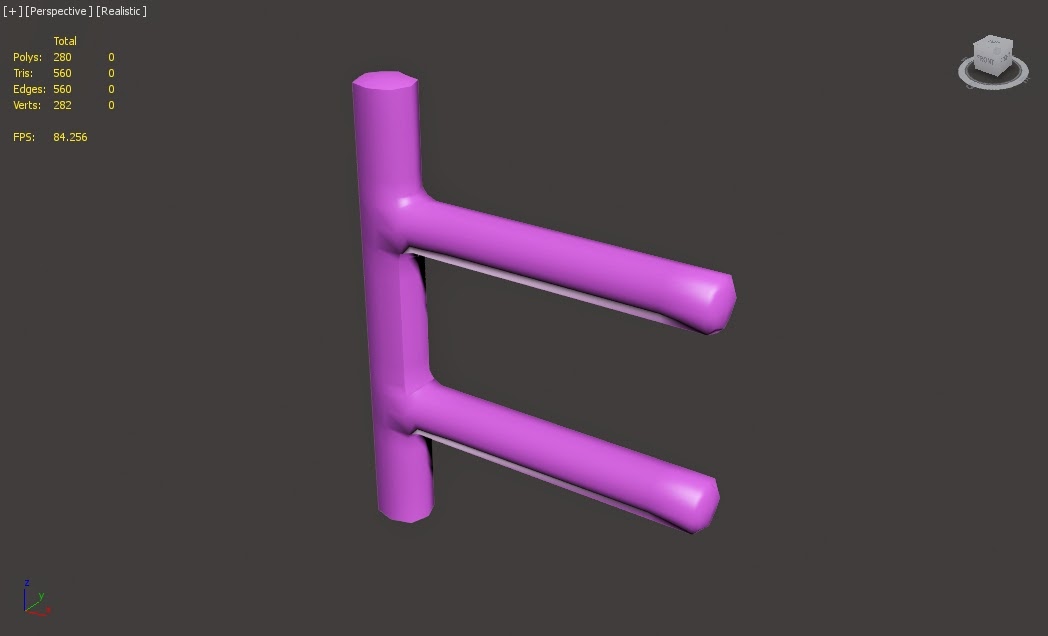
Tutorial 2: Unfortunately I couldn't find the video or user who created this tutorial, however it gives a simplified way to created connecting bars, by creating them as a box, adding hard edge loops, and then turbosmoothing the model. It came out quite rough and had smoothing issues, so its unlikely i'll be making use of this technique. 

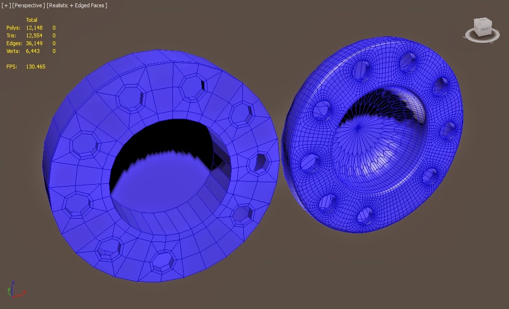
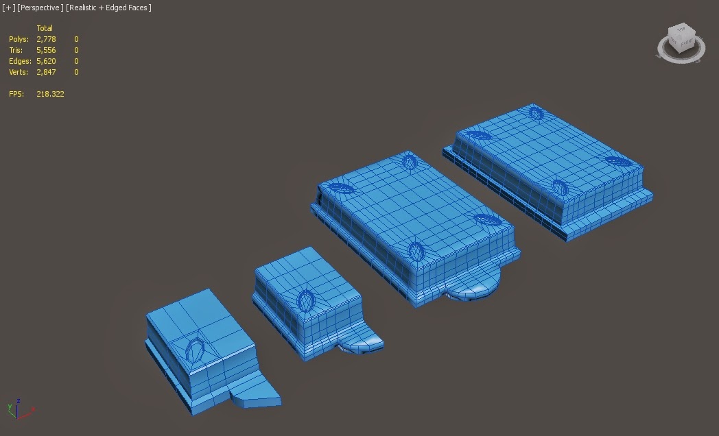
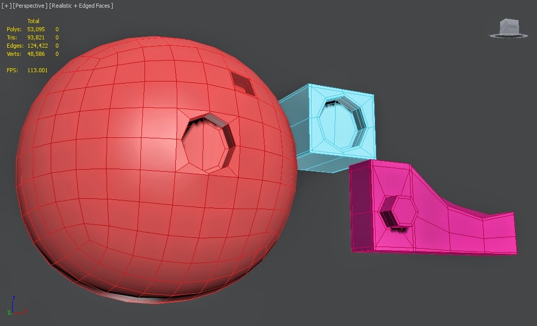
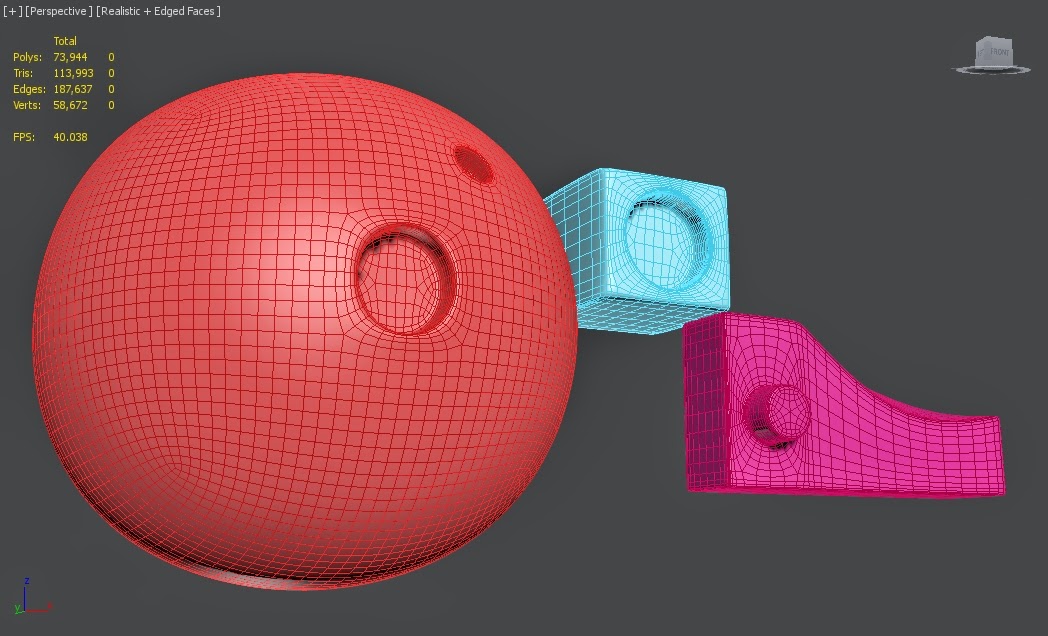
Tutorial 3: Using the Loop Tools in 3DS Max to Extrude a Circle on Any Surface- 3dmotive. By 3DSMotiveHD. This tutorial was very handy as it taught me how to create circles on surfaces without having to make use of the boolean or pro-boolean tools. To do this, I simply took a poly, created edges from each corner and side that meet up in the model, then chamfer outwards to create the circle. Then turbosmooth the model to create circle, as shown in the image below. 

Turbosmoothed version of the previous models. 

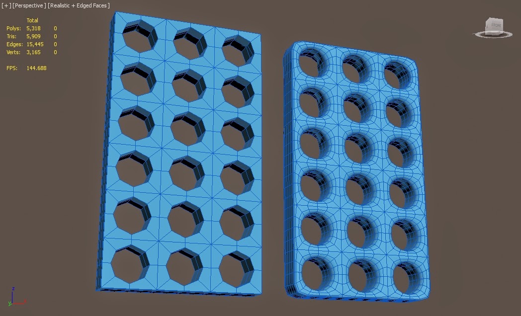
Tutorial 4: 3Ds Max. Multi Hole Selection & Creation Using Similar, Chamfer, Turbo Smooth and Prooptimizer. By Doctor Bubble. This tutorial again made use of creating circles on an object, but instead in a patterned layout. I didn't quite get the hang of it, but got the general idea through following the tutorial. This will come in handy for pieces that need to connect together. 

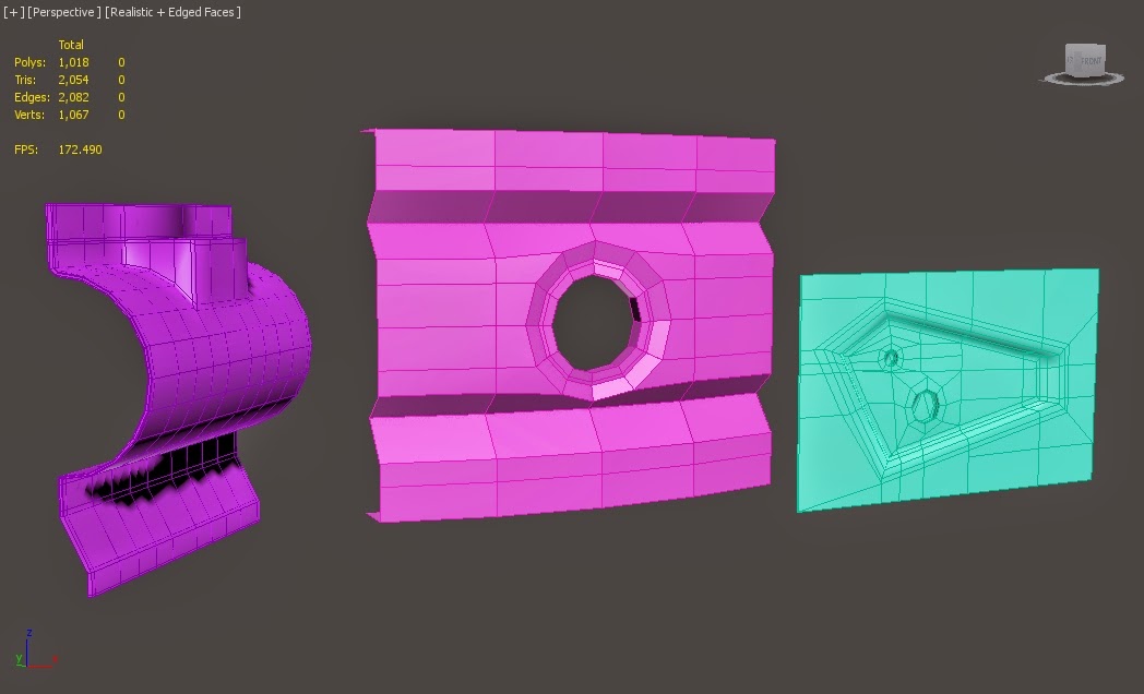
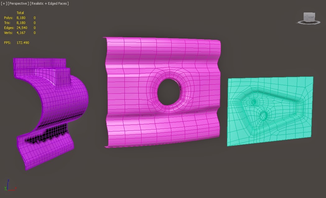
Tutorial 5: Mastering Hard Surface Lesson 007 - 3dsmax Tutorial. By FX HIVE. This tutorial video was extremely handy to follow, as it taught me how to model a lot of useful shapes that I can go on to use for my own model. It shows where to put lines to get the best results, especially when changing it from low poly to high poly via turbosmooth, but still keeping its solid shape in the process.

Example of the low poly pieces in high poly. 

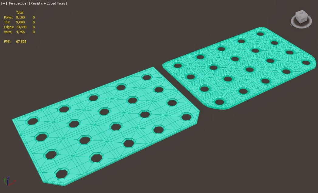
Tutorial 6: easiest way to cut holes in 3ds max. By daviti Bujiashavili.Useful for creating a multiple hole pattern for metal parts such as an engine vent. 

After looking at all these tutorials, I decided to put their techniques into practice and creating a armour piece for my military robotic mech. This took a little editing and changing a few verts and edges here and there, but overall I'm quite pleased with how this piece turned out

I also practiced making a metal vent panel through using the multiple hole technique. I found a few issues, such as multiple unconnected verts and edges appearing. However, the end result seems to work quite well for what I want. 


So having followed and practiced each of these tutorials, I feel I have learnt a few new techniques and gotten better at doing hard surface modelled. This will make modelling further on in the complex stages a lot easier to do, and in the long run have saved me a lot of time trying to figure it out. 

The next post update will contain further work done on the 3D modelling of the robotic mech.