Tuesday, 10 February 2015

Military Robotic Mech Modelling 6

In this entry I'll show you the work performed on the swap able/additional pieces that allow for the Robotic Mech to take on different job roles. Since I'm sticking more to getting the military side finished currently, Most of the pieces create have that theme in mind. As a reminder, the three vehicles types i'm focusing on are as follows:

. Main Battle Tank
. Missile Launcher Unit
. Communications Vehicle

With these three themes in mind, i'll show you what I created base off these vehicle types. Note at this point all of the pieces for the MBT were pretty much done, but since I created customisable parts, a mix and match system can be achieved similar to games like Armoured Core, which will allow for different match ups of parts to be created.

I'll split up the pieces into their main respective job roles, and into ones which are shared. Each section will come with two renders, a  blown up shot with the wireframe showing, and any major reference images used when needed.

Missile Launcher Unit

The Missile Launcher
For the ML, I knew that I wanted to make it big. As a missile unit, this variant would be tasked to rain heavy barrages of missile fire on the enemy. So I looked up reference on the internet, but couldn't find what I was looking for at first.

Then I remembered I had a certain tank image equipped with a giant missile Launcher unit when I the military references for my Image database, the TOS-1A Tank series, which had the perfect design that I wanted to reference from.

IMAGE EXAMPLE 1


IMAGE EXAMPLE 2


With this serving as a basis, I created the ML with my own design in mind, adding modular pieces previously created to speed up the modelling process. The most difficult part was making sure the hinge parts fitted onto the turret design, and didn't clash with any pieces that couldn't be swapped out.

RENDER 1 
RENDER 2

Blown up with Wireframe

In the end, I made it big and bulky, and was happy with the result.

The Anti Air guns

I also decide that I wanted to give the arm parts variations. Since this missile launcher could easily serve as an anti air unit, it would be appropriate to supply additional anti-air fire power through quadruple anti-air machine guns.

My main reference point for the machine guns was the NG7 Israel produced Heavy Machine Gun. I liked the shapes that formed its whole, so decided to use it to influence my own design. This process took a little while, especially in the turbosmoothing/hard edge editing process.

IMAGE EXAMPLE

RENDER 1

RENDER 2

Blown up with Wireframe


However once done, I replaced the Gatling gun attachment on the arm, duplicated the heavy machine gun, and attached it, as shown below.

Communications Vehicle

Extendable Torso
For a communications vehicle, I have discovered that height plays a key factor. In order to send out the radio waves required to enable communication over long distance, the higher the better. So I decided to give the communications vehicle an extendable torso, through application of a giant piston system.

This was more my own design based off of real life influences, as I couldn't really find examples of any vehicles were the cockpit extended up into the air. Cranes came close, but I did't want to implant the rigid criss-cross pattern of the metal structure.

RENDER 1

Blown up with Wireframe


This was relatively easy to do, with a lot of the shape being cylinder, which either went on to be cut up or turbosmoothed.

Satellite Arms

For the arm pieces, I wanted to create platforms that could hold small satellite dishes, to add to the idea of the communication theme. The shapes were easy enough to create, and this asset itself gave me very little trouble to do.

RENDER 1

RENDER 2

Blown Up with Wireframe


Additional Communications equipment

To further add to the communications theme, I created a few more communication pieces, to give this unit a little more variety.

RENDER 1

RENDER 2

Blown up with Wireframe

Shared

Turret Light
To replace the main turret, I decided to create a big set of lights, that could help the robotic mechs during night time scenarios. Easy enough to model, and made use of previously created modular parts.

RENDER 1

RENDER 2

Blown up with Wireframe


Hydraulic Riggers

Hydraulic riggers are used to stabalise heavy machinery, such as trucks with cranes, and hold them in place. This would be ideal for the missile and communication units, as they would need these in order to maintain their balance whilst performing their jobs. Additionally if I get the time I could also utilise it for my construction vehicle designs, which means I wouldn't need to model it again.

RENDER 1

RENDER 2

Blown up with Wireframe

Again easy to model, although difficult to find reference for at first as I didn't realise that this was their proper name.


Plough attachment

This was another shared piece that could be used for both the construction and military themes if time allows. Simple used to clear out obstacles such as debris and snow, this again made use of previously created modular parts.

RENDER 1

RENDER 2

Blown up with Wireframe


With all of these pieces created and checked through my optimisation method, I'm now ready to create the three different class types in high poly. I'll be showing these renders off in my next blog update.

The Optimisation Process

As mentioned in the last entry, this entry shows you the optimsation process I went through to add the finishing touches to my high poly model.

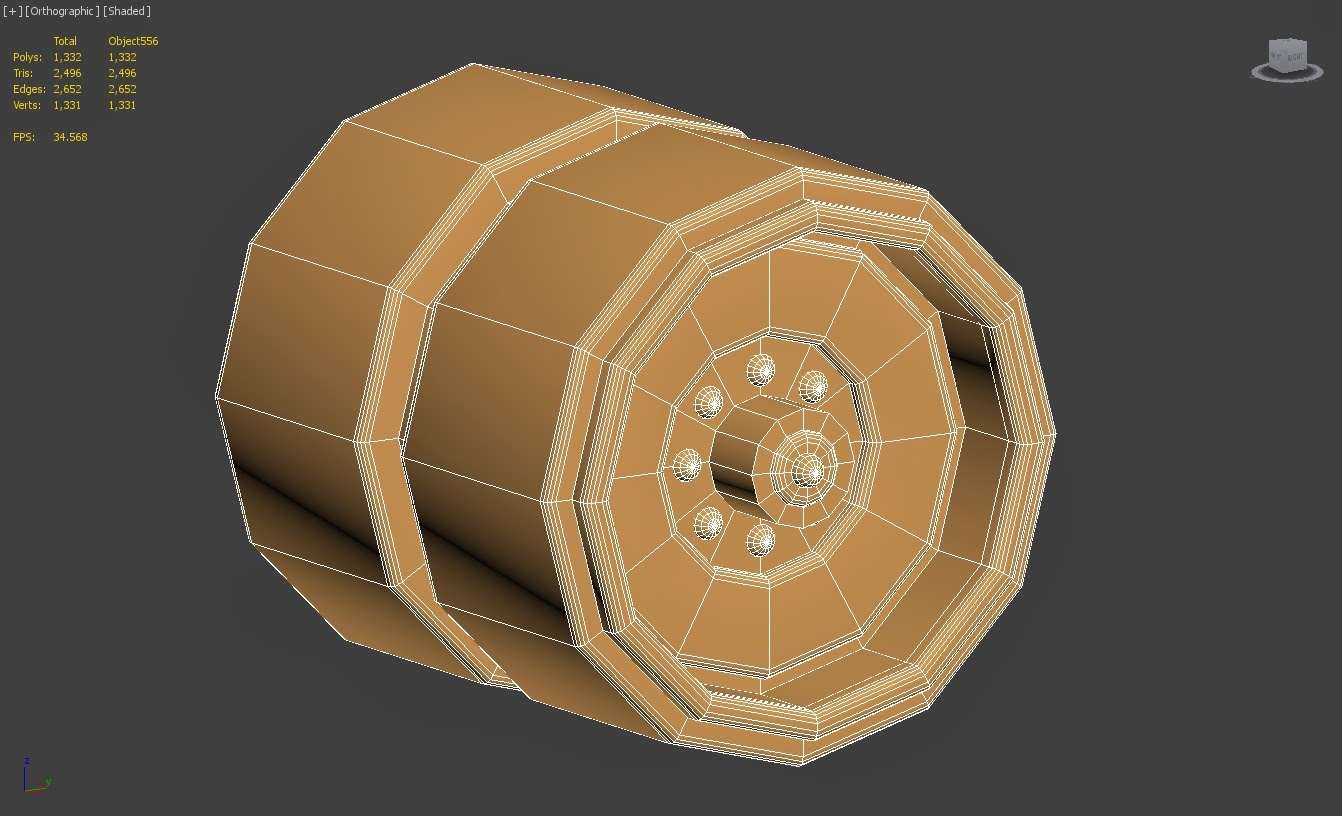
The optimisation process largely involved taking a basic model, applying a turbosmooth modifier, working out where hard edges should be placed to keep the solid shape of the original model, adjusting as needed, then removing any unnecessary edges need from the model, and putting them back in place on the original model, whilst checking for any errors through use of the numeric selection and x-view tools.

Below gives you a visual idea as to how it was done:

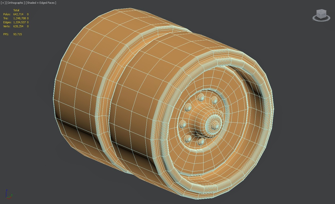
The first step was to separate the piece to be optimised from the rest of the model. In this case, one of the tank's wheels will be used as the example.
STEP 1

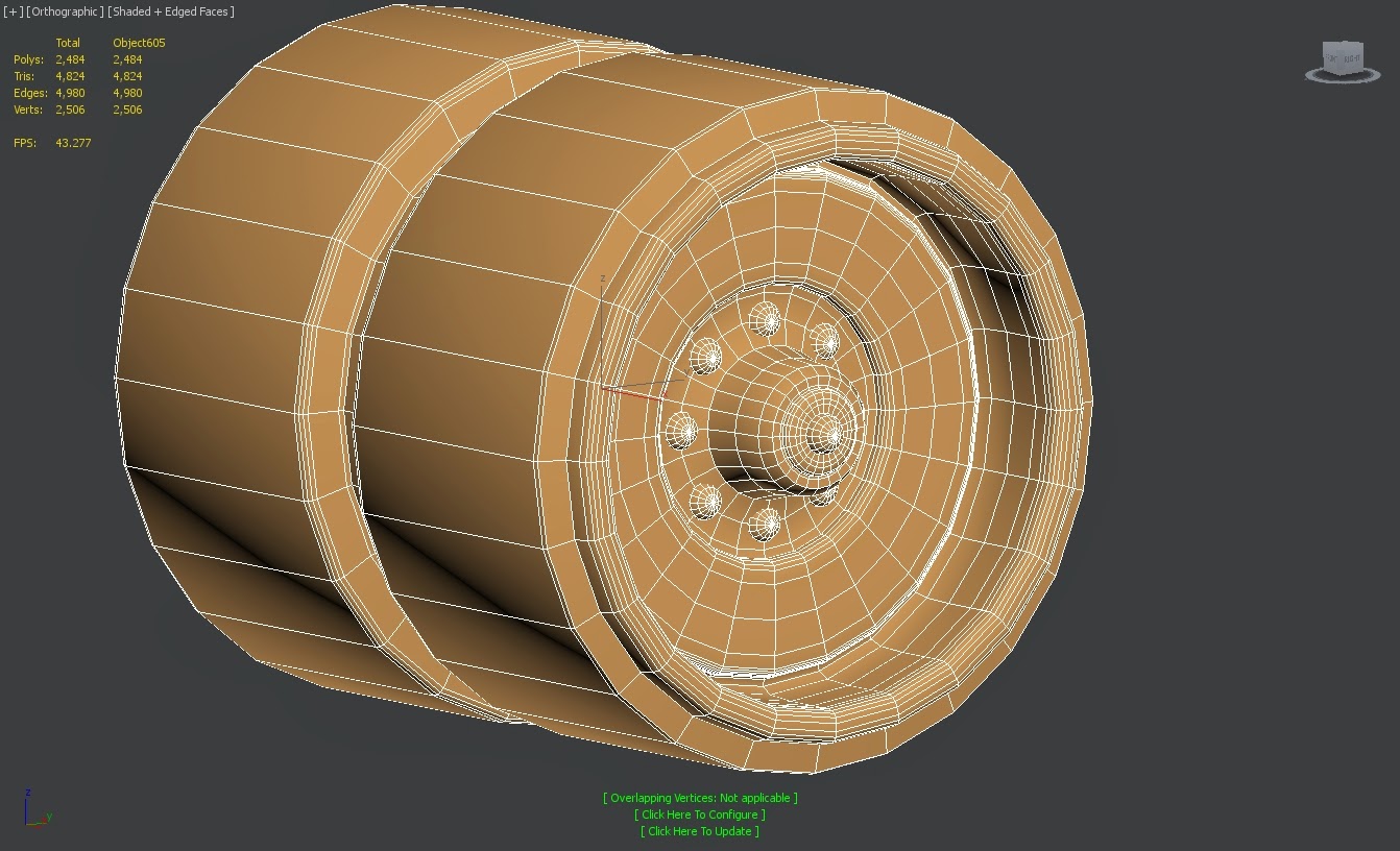
Step 2 is to apply a turbosmooth modifier one the hard edges have been put in place to keep the solid look, and then collapsed onto the lower poly model.

STEP 2

Step 3 involves removal of any unnecessary edge loops which are unneeded. This is done to reduced the overall poly, tri, vert and edge counts, as well as getting rid of any weird poly shapes created by the hard edge process.  The x-view tool is also used to look for any mistakes on the high poly model.

STEP 3


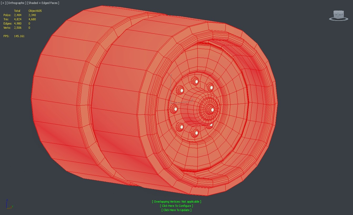
Step 4 makes use of the numeric selection checker, to pick out any n-gons or fixable triangle shapes, and these are fixed when needed.

STEP 4


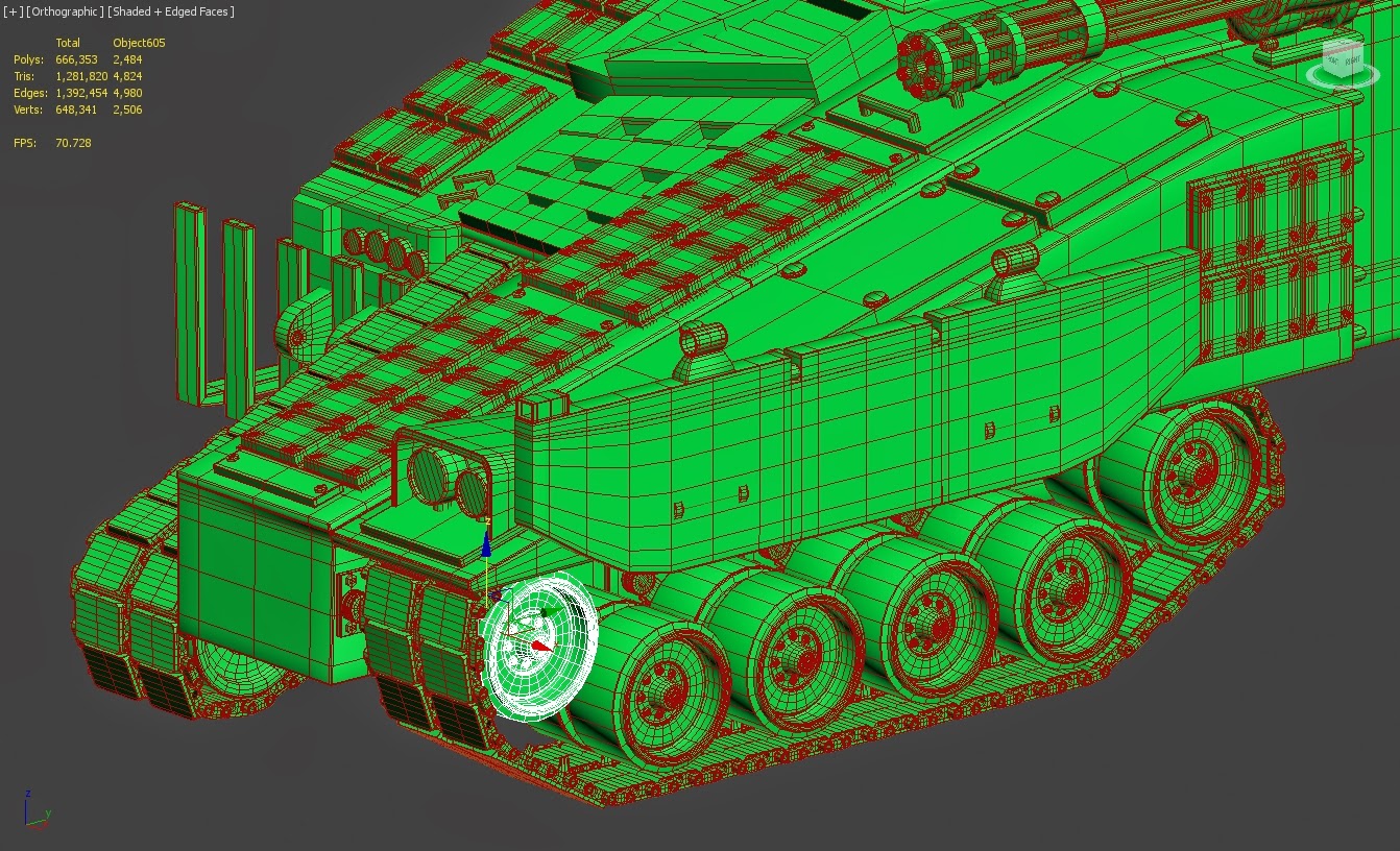
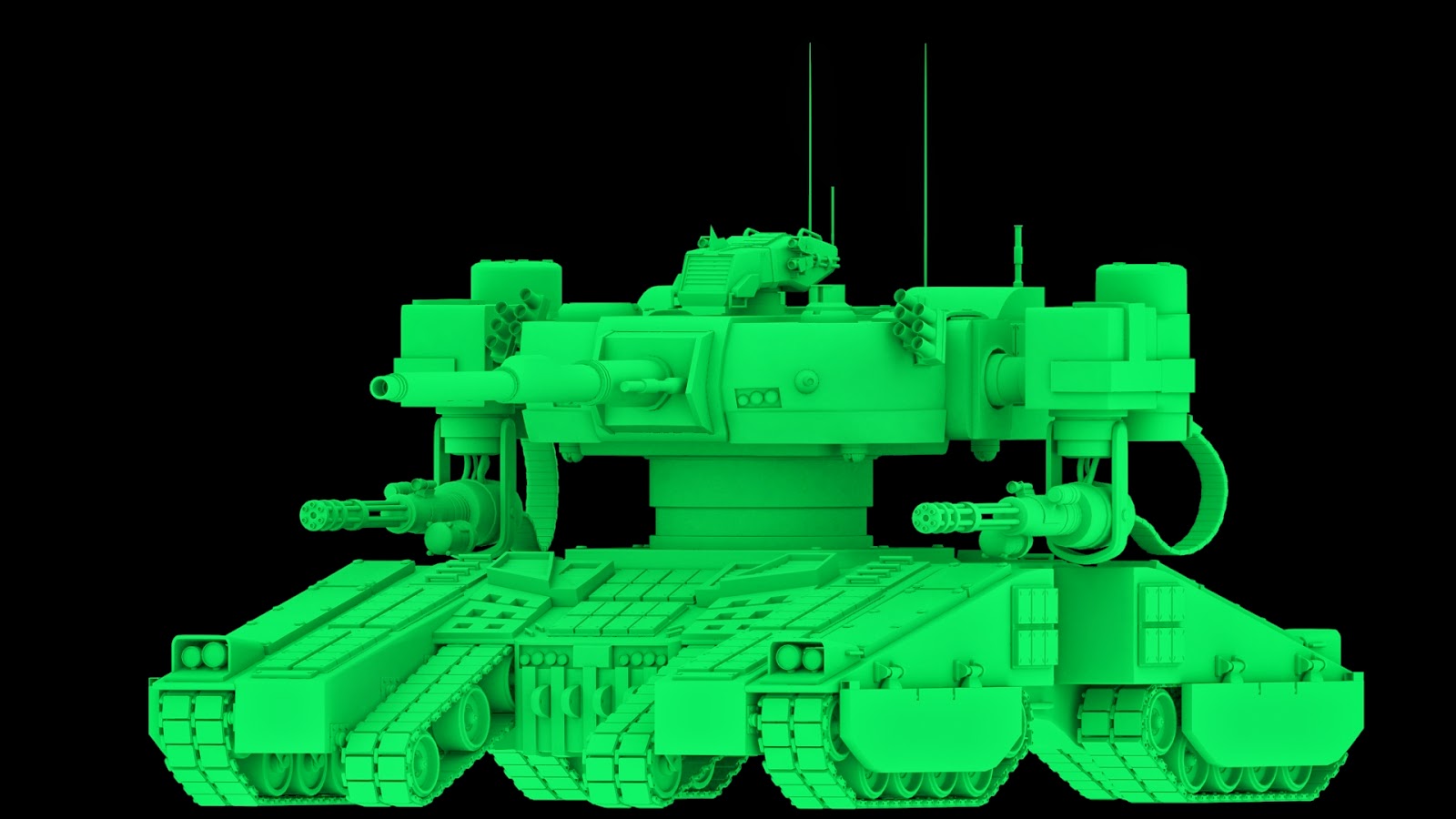
Step 5 is to change the material colour of the object to a green colour scheme, to remind me that the piece is now finished, and the model is put back in its original place. Duplications are made if the piece is modular and need to be placed in multiple places on the model.


STEP 5


Although this process was time consuming, it allowed me to properly optimise every piece of the model, which has greatly solidified the look of this model. 

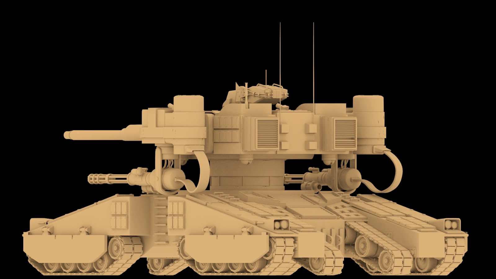
With this part done, I rendered out a few shots of the finalised model. I'm really pleased with its current look.

RENDER 1

RENDER 2


The building up of all of the main pieces for this model is now finished. The next stage, which I'll be updating in the next entry, shows the work down for the customisable pieces, that can be swapped out to create the different job classes that I mentioned back in the earlier posts.

Monday, 9 February 2015

Military Robotic Mech Modelling 5

As your saw in the last blog entry, there's been a bit of development in the modelling process. This blog will show the changes and changes made, as well as the next stages of development.

Several new pieces have been added/changed to add to the concept of the Robotic Mech. Some where for aesthetic reasons, whilst others were to try and continue the idea of realism in my work. The following list of changes/additions are listed and explained below. Note exploded views of each piece have been provided where possible to give you a good idea of the amount of pieces that go into each model:


Armour Plating:
I felt that the model was looking a little plain on the hull, so I decided to create a few modular armour pieces that could be easily placed  and give the RM a better armoured feel. This also made use of previously built modular parts, such as the bolt heads and bar frames, which has continued on the idea of modularity that I wanted to get in my model.


Lights:
These have been missing from the model for most of the building process, largely due to the fact they were easy and quick pieces to model. I created the new armoured light piece to add some variation to the hull's design and look.


Additional Cameras:
The purposes of the additional cameras are to provided the RM with additional visual information feeds, in which to take into account and use on the battlefield. Inspired by spherical secuirty cameras, they took a little time due to being unsure as to how I wanted the shape to work, but I'm happy with how this model turned out.


Side Armour:
At first I was unsure about giving this piece a high poly model, as I felt that it would lose the solid, flat look tat this armour usually has. However, through working out hard edge flow, I was able to make it work. The smaller pieces were a little more tedious, due to having to remove them and reconfigure them in order to make turbosmoothing easier in general.


Tank Hull:
The tank hull was a piece that got a lot of restructuring. The section for the second tank tread placement had been modelled wrong, in which I had to change it to a cavity instead on an inset square to get it looking right. Working out the hard edge flow took time as well, as some of the turbosmooth attempts ended up with a stretched look, which wouldn't have worked very well for when the textures would eventually be applied.


I wasn't entirely happy with the edge flow at this point, but I made changes that solved these issues, as I'll explain in the next blog update.

Tank Suspension:
The tank suspension was relatively easy, the main issue was to make sure that the connecting part to the tank wheels matched up correctly, adjusting its length as need to match it up as close as possible.


Ventilation Panels:

With a big tank comes the need for many ventalition panels, which were really easy to model. I additionally separated them from the hull model to again make the turbosmooth process easier, as well as making it easier to place them around the model as needed.


The next post will cover the optimisation process I went through with this Robotic Mech Model.

Wednesday, 4 February 2015

Military Robotic Mech Screenshots 2

Brief update on the progression of the high poly Robotic Mech. A lot of progress has been made in the past few days, with pretty much all parts of the RM now modelled. There's still a lot of optimising to do, such as removal of unnecessary edges an checking for any modelling errors, but for the most part it is ready to be taken into the unwrapping.

Below shows you some screenshots of all the current parts put together in a separate 3DS Max scene (which is how I bow render out screenshots for the full model) with a simple skylight to provide lighting and one colour gradient applied, all of which is rendered out at an HDTV size of 1920 x 1080.

Since the last entry, there have been quite a few adjustments. As shown in the front view, the tanks hull has been widen, with more detail added on.

To bolster this new detail, turbosmoothing and new pieces, such as bolted panels, were used to give the robotic mech a stronger look.

A lot of the big pieces, such as the tank hull, have been split into smaller parts and reattached to the model, to deal with any problematic topology and turbosmoothing issues. 

Its been difficult placing all the components into their correct places, which has required the use of the snaps toggle being set to vertex combined with enable axis constraints. This has allowed for a higher accuracy when placing all the parts together.

This current model stands at 749, 976 polys, 1,509,609 tris, 1,508,043 edges, and 757, 457 verts. These numbers will be reduced through the optimisation process, and will be severely reduced for the lower poly version. 

The purpose of this RM variant would be to act as a MBT unit. Alternatively, it could be used for guerilla operations or for security purpose of high-tech facilities. 

It comes equipped with a main cannon, two machine gun ports, two smoke launchers, and two Gatling gun arm attachments. It has a total of 10 optic sensors, 4 on the head, 4 on the underside of the turret, and two on the Gatling guns themselves.  

It comes packed with heavy, thick layered armour, and several blocks of reactive armour to bolster its defensive. The front and back of the vehicle can also be equipped with obstacle clearing equipment, or spare gear/ammo containers for the tank itself.

Over the course of modelling this RM I have had to make a lot of changes and adjustments from the original design. This in part is due to the ongoing research of looking at real life military vehicles, but also I've found that parts of the concept didn't translate very well to the 3D side.

However I am very happy with how the model has progressed up to this point. Although I am behind my planned schedule, I am now more confident that I can at least deliver part of the original proposal I made, whilst making changes, keeping it fresh, and still being able to deliver a satisfying end product/artefact for this project.

The next update will cover how I developed the model to its current stage in depth.

Sunday, 1 February 2015

Military Robotic Mech Screenshots

This entry is a brief showcase of the robotic mech in its entirety so far. As I've done on previous posts, this will show the whole model from varying angles, to give you a visual update on my current work.


Seeing the whole model put together shows the eventually visual impact the robotic mech will have. Safe to say i'm happy with the overall look, although would've liked to have been further ahead at this point.

I've also made a few alterations to the tanks base, mainly through removing pieces that would have clashed with the robots arms, as well as the change in the head and initial arm design. This shows that a lot of my original concept hasn't panned out as first planned, and has need changing to make it work. I am however happy with most of the changes that done so far.

The next post will contain further modelling work on this Robotic Mech design.